|
|
|
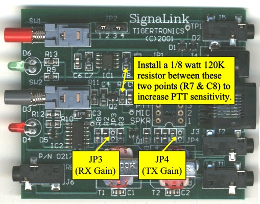
Figure 1 - This picture shows the location of jumpers JP3 (RX Gain), JP4 (TX Gain), and the resistor to install for increased PTT sensitivity. |
Because we have no control over the manner in which these modifications are performed, IF YOU WISH TO KEEP YOUR WARRANTY INTACT, THEN ALL MODIFICATIONS MUST BE PERFORMED BY TIGERTRONICS OR AN AUTHORIZED REPAIR FACILITY. You can perform these modification yourself if you feel comfortable doing so, but YOU WILL VOID THE WARRANTY. If you would like us to modify the unit for you, then please contact our Technical Support Staff for more information.
Modifications that involve soldering on the SignaLink circuit board should be done using a low-wattage (40w), static-safe soldering iron. The solder MUST be non-acid core, preferably "no clean", or a low flux solder. If "44" or other heavy flux solder is used, then you should clean the area that you soldered (NOT the whole board!) with a small amount of suitable cleaner. When cleaning the board, you should use just enough cleaner to do the job, and you need to be especially careful not to get the cleaner on the switches and connectors. All soldering and inspection should be performed at a static controlled work bench, or on an anti-static mat with adequate grounding.
This modification will increase the sensitivity of the SignaLink SL-1's PTT circuit nearly five times. All that is required is the installation of a small 1/8 watt 120K resistor between two points on the SignaLink circuit board. The resistor should be installed between resistor R7 and Capacitor C8 as shown in Figure 1 below.
NOTE: If you need to perform this modification, then you may also need to install a special jumper inside the SignaLink SL-1 that will lower the Transmit Audio attenuation, and increase the drive to the radio. Please see the "Special Jumpers" modification below.
The SignaLink circuit board (Rev B boards only) has provisions for installing two special jumpers that will increase the transmit audio and receive audio output levels. Jumper JP3 (RX Gain) can be installed to increase the receive audio going to the computer, and jumper JP4 (TX Gain) can be installed to increase the transmit audio going to the radio. Both jumper locations are clearly marked on the SignaLink circuit board and can be seen in Figure 1 below. A small piece of un-insulated solid wire can be used for the jumper, or you can install a standard 2 mm header and push-on jumper. Note that this modification is only for SignaLink SL-1 "Rev B" circuit boards, which are used in "Rev B" and "Rev C" SignaLink's. The board revision is printed on the circuit board, just left of transformer T1. The SignaLink revision is printed on the serial number sticker which is attached to the bottom of the SignaLink.
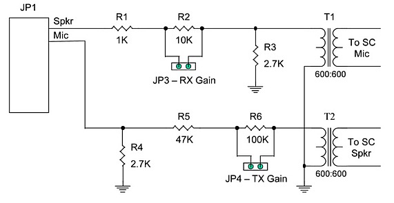
For those who may wish to experiment with the SignaLink SL-1's attenuation network, we have provided a schematic of it in Figure 2 below. Please keep in mind that the components used in the SignaLink are surface mount parts ("0805") that require special training and equipment to work with. If you need to order surface mount parts, then you will need to purchase them from an electronics parts supplier, like Mouser or DigiKey. Tigertronics does NOT sell or provide parts.
|
|
|
Figure 1 - This picture shows the location of jumpers JP3 (RX Gain), JP4 (TX Gain), and the resistor to install for increased PTT sensitivity. |
|
|
|
Figure 2 - This picture shows the SignaLink's audio
attenuation networks. The part values shown |