 |
The SignaLink has been used with virtually every radio available, but the radio that we often hear about is the Yaesu FT-817. When combined with our SignaLink USB, this wonderful little radio has proven to be very effective for portable digital QRP operation. Because of the great amount of interest that we have received in this particular equipment combination, we have decided to compile and make available all of our SignaLink / FT-817 related technical notes.
We recommend our SignaLink USB part number "SLUSB6PM". This unit comes supplied with a 6-pin mini-DIN radio cable for the FT-817's Data Port. The Data Port connection is the best way to attach the SignaLink to the FT-817, because it permits full use of all radio filters, and allows you to keep the microphone attached to the radio.
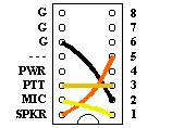
Nothing else is needed with the SignaLink USB. If you'd like to make your installation as easy as possible, then we'd suggest purchasing our optional Plug & Play Jumper Module p/n SLMOD6PM. It installs inside the SignaLink in place of the jumper wires that you would normally install (see below).
NOTE: Our optional Plug & Play Jumper Module p/n SLMOD6PM eliminates the need to install any jumper wires.
The jumper settings shown below are for use with our SignaLink USB p/n: SLUSB6PM which includes our 6-pin mini-DIN Data Port radio cable p/n SLCAB6PM. If you are using a home-built radio cable, your cable MUST be wired the same as ours, or these jumper settings will not work (see cable wiring diagram below).
 |
NOTE: Our radio cable p/n SLCAB6PM is fully assembled and insert-molded for excellent durability. We strongly recommend purchasing it over building your own cable - especially for portable operation!
For those customers that would like to build their own radio cable, we have
provided the wiring information that you will need below. Note that our
radio cable is wired "straight through" (pin #1 to pin #1, pin #2 to
pin #2, etc.). We suggest that you wire your cable the same way, so that
you will be able to use the same jumper settings that are shown in our support
documentation. Before you begin assembly of your cable, we also suggest that you carefully review
the pictures of the RJ-45 and 6-pin mini-DIN connectors that are shown below. Be sure that you
clearly understand where each pin is located, as it is very easy to get things
reversed!
|
RJ-45 (SignaLink) |
Wire Color |
6-pin mini-DIN (FT-817) |
| Pin #1 | Black |
Pin #1 |
| Pin #2 | Brown |
Pin #2 |
| Pin #3 | Red |
Pin #3 |
| Pin #4 | Orange | Pin #4 |
| Pin #5 | Yellow | Pin #5 |
| Pin #6 | Green | Pin #6 |
| Pin #7 | NC | Pin #7 |
| Pin #8 | NC | Pin #8 |
|
Pin-out For FT-817 Data Port Connector |
|---|
 |
| NOTE: This drawing is looking into the JACK on the FT-817 (NOT the plug). |
| Pin Numbering For SignaLink RJ-45 |
|---|
|
|
| NOTE: This picture is looking into the back of the RJ-45 with the Release Tab on top. |
For PSK31 and other digital modes that use USB, you should set the FT-817 to “User-U” (see radio manual for menu setting) and select "Digi" mode to access it. This will allow you to operate without any unintentional frequency offset, or you can adjust for any offset desired using menu items 24 and 27. Note that the FT-817 has a number of menu items to control the input audio levels during transmit, and one very important setting to control the Receive Audio output. A brief description of each of these is listed below.
25 - DIG MIC - Adjust this to increase/decrease the radio's input sensitivity on Transmit while in the "Digital" mode. This will interact with the SignaLink USB's TX knob.
39 - PKT MIC - Adjust this to increase/decrease the radio's input sensitivity on Transmit while in the "Packet" Mode (normally used on VHF). This will interact with the SignaLink USB's TX knob.
40 - PKT RATE - This must be set to 1200 baud.