See our
SignaLink
USB Product Guide
to find the part numbers
for your
radio
or give
us a call at (800) 822-9722 (Mon - Fri, 9AM - 5PM PST / 12PM - 8PM PST).
| FREE SHIPPING on U.S. orders of $99 or more + reduced rates to most countries! |
|
|
|
See our
SignaLink
USB Product Guide
to find the part numbers
for your
radio |
Updated: April 6, 2025
Select
The Correct Diagram -
When
viewing the jumper settings below, please take a moment to
BE CERTAIN THAT
YOU ARE LOOKING AT THE CORRECT DIAGRAM for the radio connector
that you will be connecting the SignaLink to. For any given radio, there are likely to be a
different jumper settings for the Mic, Data and Accessory connectors. This
means that the first diagram you come to for your radio model could be the
wrong one, so please look carefully!
Jumper Wires vs
Jumper Modules - The SignaLink USB
can be configured with either jumper wires or an optional Jumper Module.
Jumper Modules are available for most radios and greatly simplify
installation. Please see our
SignaLink
USB Product Guide to find the jumper module that is needed for your
installation.
RX Control
Line (RXCTRL) -
The latest revision of the SignaLink USB provides an "RXCTRL" line
in addition to a standard PTT line. A number of popular and
inexpensive 10m, 11m, and 12m radios use both PTT and RXCTRL to switch
between Receive and Transmit. Previous versions of
the SignaLink USB, as well as earlier SignaLink models, do not provide this feature, so your SignaLink's
JP1 socket may not
show the "RXCTRL" pin as depicted in the jumper settings below. If
your radio requires this control line then you will need to upgrade to the latest
SignaLink USB. If your radio does not use the RXCTRL line, then you
can simply ignore it.
PTT
Voltage & Current Limits - If you are using an older tube
based radio, or an uncommon radio that is not normally connected to devices
like the SignaLink or a TNC (etc.), then you should verify in your radio manual that the
radio PTT requirements do not exceed the specifications of the SignaLink
keying circuit (please refer to the SignaLink manual), and that the PTT line is “Grounded” to make the radio
transmit. If your radio exceeds the specifications listed or requires some other
keying arrangement, then please contact our Technical Support Staff for
suggestions.
RECEIVE AUDIO / SPEAKER AUDIO
-
Receive
Audio is available on the Mic, Data, and Accessory Port connectors of most
radios. If Receive Audio is not shown in the jumper settings for your
radio (this is the "SPK" jumper) or if it is noted that only some radios may
provide this signal, then you will need to check your radio manual to see if it is available. If it
is not available, then do NOT install the SPK jumper wire. Instead,
you will need to connect the supplied audio cable between your radio's
External Speaker or Headphone jack, and the SPKR jack on the
back of the SignaLink. Please see the SignaLink USB Installation Manual for
details.
Jumper
Installation for the older SignaLink "SL-1" and "SL-1+" models
-
The jumper settings shown below are for the SignaLink USB. However, the
jumper settings for any radio Microphone connection should also work with the
SL-1 and SL-1+, assuming that the radio uses a single standard PTT line only
(the SL-1 and SL-1+ do not provide an RXCTRL line). For installation of the
PWR jumper on the older SL-1 and SL-1+ models, please refer to the SignaLink SL-1
or SL-1+ Installation Manual.
RJ-45 Mic Connectors -
There is a lack of
standardization in the way that radio manufacturers number their RJ-45 Mic
connectors. We have numbered our connector according to the dominant
industry standard (as shown below), and all jumper settings shown in our
documentation reflect this standard. Icom follows
this standard, but Kenwood, Yaesu and some others do not. All of
the jumper settings show below have been corrected as necessary to account
for any reversed pin numbering. If your
radio is not shown below and you need to figure out your own jumper
settings, then you will need to carefully determine how
your mic connector is
numbered to avoid reversing the connections!
 |
| Industry Standard RJ-45 Pin Numbering
used by SignaLink & Icom. Kenwood, Yaesu and some others do not follow this standard. |
Please read the "Important Notes" above BEFORE you select your jumper settings. This will save time and it may help prevent you from making a mistake that could possibly damage the SignaLink or your radio.
NOTE: If you are looking for part number information for your radio, then please see our SignaLink USB Product Guide.
8-Pin Round Mic Connector - Use SignaLink USB p/n SLUSB8R or radio cable p/n SLCAB8R
| SignaLink USB Jumper Socket | Pin-out | Radio Models | Notes |
|---|---|---|---|
|
|
Pin 1 - Mic Input Pin 2 - PTT Pin 3 - N/C Pin 4 - N/C Pin 5 - N/C Pin 6 - Speaker** Pin 7 - N/C Pin 8 - GND |
AR-146 AR-147 AR-446 |
**Speaker audio is available on pin #6 of some radio models. Check your radio manual and install the SPK jumper to pin #6 only if this signal is provided. If it is not, then you will need to connect the supplied audio cable as outlined in the SignaLink USB manual. |
8-Pin Round Mic Connector - Use SignaLink USB p/n SLUSB8R or radio cable p/n SLCAB8R
| SignaLink USB Jumper Socket | Pin-out | Radio Models | Notes |
|---|---|---|---|
|
|
Pin 1 – Mic Input Pin 2 – PTT Pin 3 – N/C Pin 4 – N/C Pin 5 – N/C Pin 6 – N/C** Pin 7 – GND Pin 8 – GND |
ALD-24T ALR-22T ALR-22HT ALR-72T DR-110T DR-112T DR-130T DR-135E DR-135T DR-150 DR-235T DR-430T DR-435E DR-435T DR-510T DR-570T DR-590T DR-592T DR-599T DR-600T DR- DR-610T DR-620E DR-620T DR-635 DR-1200 DR-B185HT DR-B185HE DX-70 DX-70T DX- DX-70EH DX-77 DX-SR8T DX-SR8E DX-SR9 |
**Speaker audio is available on pin #6 of some radio models. Check your radio manual and install the SPK jumper to pin #6 only if this signal is provided. If it is not, then you will need to connect the supplied audio cable as outlined in the SignaLink USB manual. |
RJ-45 Mic Connector - Use SignaLink USB p/n SLUSBRJ4 or radio cable p/n SLCABRJ4
| SignaLink USB Jumper Socket | Pin-out | Radio Models | Notes |
|---|---|---|---|
|
|
Pin 1 – N/C Pin 2 – N/C Pin 3 – N/C Pin 4 – PTT Pin 5 – Mic GND Pin 6 – Mic Input Pin 7 – GND Pin 8 – N/C |
DR-140 DR-605E DR-605T DR-735T DR-735E |
Speaker audio is available on
the mic jack of some radio models. Check
your radio manual and install the SPK jumper only if this signal is
provided. If it is not, then you will need to connect the supplied audio
cable as outlined in the SignaLink USB manual.
|
6-pin Mini-DIN Data Port - Use SignaLink USB p/n SLUSB6PM or radio cable p/n SLCAB6PM
| SignaLink USB Jumper Socket | Pin-out | Radio Models | Notes |
|---|---|---|---|
|
|
Pin 1 – Data In Pin 2 – Ground Pin 3 – PTT Pin 4 – 9600 Out Pin 5 – 1200 Out Pin 6 – Squelch |
DR-735T DR-735E |
For VHF/UHF modes that require 9600 baud audio (VARA FM Wide, etc.), you will need to move the SPK jumper to pin #4 and configure your radio for 9600 baud audio (see your radio manual for details). |
RJ-45 Mic Connector - Use SignaLink USB p/n SLUSBRJ4 or radio cable p/n SLCABRJ4
| SignaLink USB Jumper Socket | Pin-out | Radio Models | Notes |
|---|---|---|---|
|
|
Pin 1 – Mic Input Pin 2 – GND Pin 3 – N/C Pin 4 – N/C Pin 5 – N/C Pin 6 – N/C Pin 7 – PTT Pin 8 – N/C |
AT-778UV | There are two
options for getting Receive Audio into the SignaLink when using the AT-778UV; External Speaker jack or Mic jack "HAND" audio. Please READ CAREFULLY BEFORE deciding which option you want to use as both require a little special consideration. Note that you use one option or the other - you do NOT use both at the same time. External Speaker - To use the External Speaker jack, you MUST connect it to the SignaLink's SPKR jack via an inexpensive external isolation/ground loop adapter (available from Amazon and other sources). The External Speaker jack on this radio CANNOT be connected directly to the SignaLink as this will short out one side of the radio's audio amplifier and possibly damage it. If you use this option, then you DO NOT install the below mentioned capacitor as it's not used. Mic Jack HAND Audio - To use the RX Audio signal that is present on the mic jack, you'll need to make the "SPK - 4" jumper connection show in the jumper diagram using a 4.7uf to 47uf (16VDC or better rating) capacitor instead of a jumper wire. Connect the + side of the cap to pin #4. Be sure the leads on your cap are the same size as our jumper wires, or you'll damage the JP1 socket. If needed, cut a jumper wire in half and solder it to each leg of the cap and then plug that into the socket. Once you've made the jumper connection using a suitable capacitor, then you must set radio Function Menu #16 to "HAND" to enable RX Audio on the RJ45 mic connector. |
8-Pin Round Mic Connector - Use SignaLink USB p/n SLUSB8R or radio cable p/n SLCAB8R
| SignaLink USB Jumper Socket | Pin-out | Radio Models | Notes |
|---|---|---|---|
|
|
Pin 1 – Mic Input Pin 2 – GND Pin 3 – N/C Pin 4 – N/C Pin 5 – N/C Pin 6 – N/C Pin 7 – PTT Pin 8 – N/C |
PCS
5000 PCS 6000 PCS 7000 |
Speaker audio is available on the mic jack of some radio models. Check your radio manual and install the SPK jumper only if this signal is provided. If it is not, then you will need to connect the supplied audio cable as outlined in the SignaLink USB manual. |
4-Pin Round Mic Connector - Use SignaLink USB p/n SLUSB4R or radio cable p/n SLCAB4R
| SignaLink USB Jumper Socket | Pin-out | Radio Models | Notes |
|---|---|---|---|
|
|
Pin 1 – Mic Input Pin 2 – PTT Pin 3 – GND Pin 4 – N/C |
TR-7 TR-22 TR-33 UV-3 |
Speaker audio is not available on the mic jack of these radios, so you will need to connect the supplied audio cable as outlined in the SignaLink USB manual. |
8-Pin Round Mic Connector - Use SignaLink USB p/n SLUSB8R or radio cable p/n SLCAB8R
| SignaLink USB Jumper Socket | Pin-out | Radio Models | Notes |
|---|---|---|---|
|
|
Pin 1 - Mic
Pin 2 - PTT Pin 3 - NC Pin 4 - NC Pin 5 - NC Pin 6 - +5VDC Pin 7 - GND Pin 8 - GND |
K2** K3 K3/S |
K2 - The Mic jack on this radio can be wired a number of different ways. BEFORE installing the jumper wires, you MUST verify that the pin-out of your K2 matches that shown here. |
Elecraft K3 and K4 rear panel Audio In, Audio Out and PTT connectors - Use SignaLink USB p/n SLUSBK3 or radio cable p/n SLCABK3
| SignaLink USB Jumper Socket | Pin-out | Radio Models | Notes |
|---|---|---|---|
|
|
Pin 1 - SPKR
Pin 2 - GND Pin 3 - Mic Pin 4 - PTT Pin 5 - GND Pin 6 - GND Pin 7 - NC Pin 8 - NC |
K3** K3S** K4 |
K3 - Some customers have found that the K3's "Line In" gain (menu setting) is set to zero by default, thereby resulting in no power output when transmitting. If you experience this problem, then please consult your radio manual for instructions on adjusting this setting. |
Elecraft KX2 and KX3 Mic connector - Use SignaLink USB p/n SLUSBKX3 or radio cable p/n SLCABKX3
| SignaLink USB Jumper Socket | Pin-out | Radio Models | Notes |
|---|---|---|---|
|
|
Pin 1 - Mic
Pin 2 - PTT Pin 3 - GND Pin 4 - NC Pin 5 - NC Pin 6 - NC Pin 7 - NC Pin 8 - NC |
KX2
KX3 |
KX2/KX3 Radio Settings: 1 - The “Mic Bias” setting in the KX2/KX3’s menu system should be turned OFF if you are using jumper wires. This setting can be left ON if you are using our SLMODKX3 jumper module, as it has a built-in DC blocking capacitor. 2 - The “Mic Btn” setting should be set to either “PTT”, or “PTT Up.Dn.”. 3 - We recommend turning the KX2/KX3’s “Audio Effects” feature OFF, as it will likely cause receive problems during digital operation. |
4-Pin Round Mic Connector - Use SignaLink USB p/n SLUSB4R or radio cable p/n SLCAB4R
| SignaLink USB Jumper Socket | Pin-out | Radio Models | Notes |
|---|---|---|---|
|
|
Pin 1 – Mic Input Pin 2 – PTT Pin 3 – N/C Pin 4 – GND |
IC-22 IC-202 IC-215 IC-245 IC-280 IC-402 IC-502 IC-551 IC-701 |
Speaker audio is not usually available on 4-pin mic jacks. Check your radio manual and install the SPK jumper only if this signal is provided. If it is not, then you will need to connect the supplied audio cable as outlined in the SignaLink USB manual. |
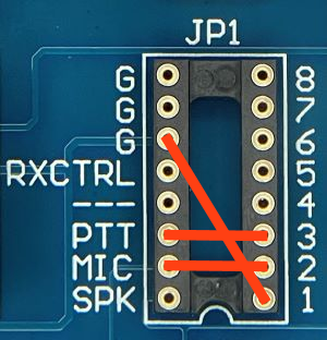
8-Pin Round MIC Connector - Use SignaLink USB p/n SLUSB8R or radio cable p/n SLCAB8R
IMPORTANT: This diagram is for the MIC JACK only. If the SignaLink is attached to your radio's 8-pin Accessory Port, then please see the diagram below under "8-pin DIN Accessory Port Connector".
| SignaLink USB Jumper Socket | Pin-out | Radio Models | Notes |
|---|---|---|---|
|
|
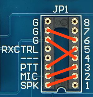
Pin
1 – Mic Input Pin 2 – N/C Pin 3 – N/C Pin 4 – N/C Pin 5 – PTT Pin 6 – GND Pin 7 – GND Pin 8 – Speaker** |
IC-22U IC-25 IC-27 IC-28 IC-37A IC-38A IC-45 IC-47 IC-48 IC-228 IC-229 IC-251A IC-251E IC-255 IC-260 IC-271 IC-290 IC-375 IC-471 IC-475 IC-490 IC-505 IC-551 IC-560 IC-575 IC-707 IC-718 IC-720 IC-725 IC-726 IC-728 IC-729 IC-730 IC-735 IC-736 IC-737 IC-738 IC-740 IC-745 IC-746 IC-746PRO IC-751 IC-756 IC-756PRO IC-756PROII IC-756PROIII IC-761 IC-765 IC-775 IC-781 IC-820H IC-901 IC-910H IC-1201 IC-1271 IC-1275 IC-2400 IC-2500 IC-3200 IC-3210 IC-3220 IC-3230 IC-7300 IC-7400 IC-7410 IC-7600 IC-7700 IC-7800 IC-9100 |
**Speaker audio is available on
pin #8 on some radio models. Check
your radio manual and install the SPK jumper only if this signal is
provided on pin #8. If it is not, then you will need to connect the supplied audio
cable as outlined in the SignaLink USB manual.
|
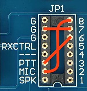
RJ-45 Mic Connector - Use SignaLink USB p/n SLUSBRJ4 or radio cable p/n SLCABRJ4
| SignaLink USB Jumper Socket | Pin-out | Radio Models | Notes |
|---|---|---|---|
|
|
Pin
1 – +8V Pin 2 – N/C Pin 3 – Speaker** Pin 4 – PTT Pin 5 – GND (mic) Pin 6 – Mic Input Pin 7 – GND Pin 8 – N/C |
IC-207H** IC-208H** IC-281A IC-281E IC-281H IC-703 IC-706 IC-706MKII IC-2000 IC-2100H** IC-2200H** IC-2300H** IC-2700** IC-2720H** IC-2730A** IC-2730E** IC-2800** IC-2820** IC-7000** IC-7100** IC-A120 IC-A120E IC-V8000** ID-800H** ID-880** ID-4100A ID-4100E** ID-5100A ID-5100E** |
**Speaker audio is available on
pin #3 on some radio models. Check
your radio manual and install the SPK jumper only if this signal is
provided on pin #3. If it is not, then you will need to connect the supplied audio
cable as outlined in the SignaLink USB manual. **Speaker Audio is not available on the Mic jack of this radio, so do NOT install the SPK jumper wire. Instead, you will need to connect the supplied audio cable as outlined in the SignaLink USB manual. |
6-pin Mini DIN Data Port Connector - Use SignaLink USB p/n SLUSB6PM or radio cable p/n SLCAB6PM
| SignaLink USB Jumper Socket | Pin-out | Radio Models | Notes |
|---|---|---|---|
|
|
Pin 1 – Data In Pin 2 – Ground Pin 3 – PTT Pin 4 – 9600 Out Pin 5 – 1200 Out Pin 6 – Squelch |
IC-208H IC-703** IC-706MKIIG** IC-746PRO** IC-910H** IC-2720H IC-2800** IC-2820 IC-7000** IC-7100 IC-7400 IC-9100 ID-880 |
For VHF/UHF modes that require 9600 baud audio
(VARA FM Wide), you will need to move the SPK jumper to pin #4 and configure
your radio for 9600 baud audio (see your radio manual for details). IC-703 - Radio menu #36 should be set to "1200". IC-706MKIIG - Radio menu #29 should be set to "1200" for both HF operation and for VHF/UHF operation with digital modes other than VARA FM Wide. For the VARA FM Wide mode, you must set menu #29 to "9600" and move the SPK jumper to pin #4. IC-746PRO / IC-7000 - Some users have reported that this radio has a very sensitive Data Port, making power adjustments with the SignaLink USB's TX knob somewhat touchy. If this is the case with your radio, then please click here for a simple solution. IC-910H - You will need to connect the SignaLink to the "Main" data port connection on this radio (not the "Sub" port). IC-2800 - Mic audio is NOT muted on this radio so you'll need to unplug your microphone. |
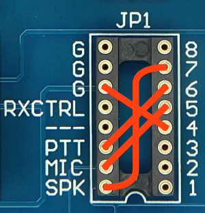
8-pin DIN Accessory Port Connector - Use SignaLink USB p/n SLUSB8PD or radio cable p/n SLCAB8PD
IMPORTANT: This diagram is for the ACCY PORT only. If the SignaLink is attached to your radio's 8-pin Round Mic Jack, then please see the diagram above under "8-Pin Round MIC Connector".
| SignaLink USB Jumper Socket | Pin-out | Radio Models | Notes |
|---|---|---|---|
|
|
Pin 1 - RTTY or N/C Pin 2 - Ground Pin 3 - Send (PTT) Pin 4 - Mod In Pin 5 - AF Out Pin 6 - Squelch Pin 7 - +13.8V Pin 8 - ALC |
IC-475 IC-575A IC-575H IC-707 IC-725 IC-726 IC-728 IC-729 IC-735 IC-736 IC-737 IC-738 IC-746** IC-746PRO** IC-756 IC-756PRO** IC-756PRO II** IC-756PRO III** IC-761 IC-765 IC-775 IC-775DSP IC-781 IC-820H** IC-821H IC-910H IC-970 IC-7400 IC-7600 IC-7610 IC-7700 IC-7800 IC-9700 IC-M600 IC-M700PRO IC-M710 IC-M802 |
IC-746 (non-Pro model) - This radio
may not mute the Mic when keyed from the ACC Port,
so you may need
to turn the Mic Gain down or unplug the microphone. The ACC jack on
this radio does NOT support VHF operation. For VHF operation you must
connect the SignaLink to
the mic jack. IC-746PRO - This radio MUST be set to a digital mode like "D-USB" or "D-LSB", or transmit will not work properly. The ACC jack on this radio does NOT support VHF operation. For VHF operation you must connect the SignaLink to the 6-pin Data Port or the mic jack. IC-756PRO/II/III - This radio MUST be set to a digital mode like "D-USB" or "D-LSB", or transmit will not work properly. IC-820H - The Modulation Input Sensitivity switch should be set to "Low" and the Baud Rate Selection switch should be set to "AMOD". |
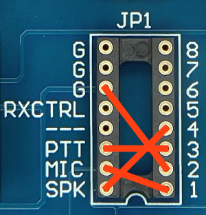
13-pin DIN Accessory Port Connector - Use SignaLink USB p/n SLUSB13I or radio cable p/n SLCAB13I
NOTE: The 13-pin ACC jack on the IC-275, IC-475 and IC-970 CANNOT be used with our SLCAB13I cable due to it's non-standard pin-out - DAMAGE TO THE SIGNALINK OR RADIO MAY OCCUR! On these radios you will need to attach the SignaLink to the mic jack or to a different ACC port if available.
| SignaLink USB Jumper Socket | Pin-out | Radio Models | Notes |
|---|---|---|---|
|
|
Our radio cable p/n SLCAB13I is wired to use the jumper settings shown. |
IC-703 IC-706** IC-706MKII** IC-706MKIIG** IC-718** IC-7000** IC-7100** IC-7200 IC-7300 IC-7410 IC-9100 |
IC-706 - For VHF/UHF operation
you must move the PTT
jumper to Pin #4. IC-706MKII - For VHF/UHF operation you must move the PTT jumper to Pin #4. IC-706MKIIG - For VHF/UHF operation you must turn the radio's "VSEND" menu #30 to OFF. This will force the radio to use the HF PTT pin for all bands so you won't need to change jumper settings. IC-718 - This radio does NOT mute the Mic jack when using the 13-pin ACC Port, so you will need to turn the Mic Gain down.IC-7000 - For VHF/UHF operation you must turn the radio's "VSEND" menu #20 to OFF. This will force the radio to use the HF PTT pin for all bands so you won't need to change jumper settings. This radio does not mute the mic jack when using the 13-pin ACC port, so you will need to turn the Mic Gain down or use the 6-pin Data Port instead. IC-7100 - This radio does not mute the mic jack when using the 13-pin ACC port, so you will need to turn the Mic Gain down or use the 6-pin Data Port instead. |
24-pin DIN Accessory Port Connector - We do not manufacture a cable for the ICOM 24-pin Accessory Port connector but you can easily build your own using our un-terminated radio cable p/n SLCABNC. To build your cable, simply wire it straight-through for pin numbers 1-8 (Pin #1 to Pin #1, Pin #2 to Pin #2, etc.). Note that your cable MUST wired straight-through or the jumper settings shown below will NOT work, and you might DAMAGE YOUR RADIO OR THE SIGNALINK!
| SignaLink USB Jumper Socket | Pin-out | Radio Models | Notes |
|---|---|---|---|
|
|
Pin 1 - NC Pin 2 - +13.8V Pin 3 - PTT Pin 4 - AF Out Pin 5 - Mic Input Pin 6 - NC Pin 7 - NC Pin 8 - GND Pins 9-24 NC |
IC-730 IC-751 |
Pins marked as "NC" are not used by the SignaLink, but might be connected internally inside the radio. |
8-Pin Round Mic Connector - Use SignaLink USB p/n SLUSB8R or radio cable p/n SLCAB8R
| SignaLink USB Jumper Socket | Pin-out | Radio Models | Notes |
|---|---|---|---|
|
|
Pin 1 - N/C Pin 2 - N/C Pin 3 - N/C Pin 4 - +9V Pin 5 - GND Pin 6 - PTT Pin 7 - Mic GND Pin 8 - Mic Input |
JST-145 JST-245 |
Speaker audio is not available on the mic jack of these radios, so you will need to connect the supplied audio cable as outlined in the SignaLink USB manual. |
4-Pin Round Mic Connector - Use SignaLink USB p/n SLUSB4R or radio cable p/n SLCAB4R
| SignaLink USB Jumper Socket | Pin-out | Radio Models | Notes |
|---|---|---|---|
|
|
Pin 1 – Mic Input Pin 2 – PTT Pin 3 – GND Pin 4 – Mic GND |
TR-7200A TR-7400A TR-7500 TS-120S TS-130S TS-180S TS-511S TS-520 TS-530 TS-600 TS-700 TS-820 TS-830 |
Speaker audio is not usually available on 4-pin mic jacks. Check your radio manual and install the SPK jumper only if this signal is provided. If it is not, then you will need to connect the supplied audio cable as outlined in the SignaLink USB manual. |
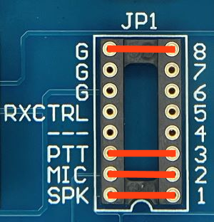
8-Pin Round Mic Connector - Use SignaLink USB p/n SLUSB8R or radio cable p/n SLCAB8R
| SignaLink USB Jumper Socket | Pin-out | Radio Models | Notes |
|---|---|---|---|
|
|
Pin
1 – Mic Input Pin 2 – PTT Pin 3 – N/C Pin 4 – N/C Pin 5 – 8 VDC Pin 6 – Speaker** Pin 7 – Mic GND Pin 8 – GND |
TM-201 TM-211 TM-221 TM-231 TM-241 TM-321 TM-331 TM-401 TM-421 TM-431 TM-441 TM-521 TM-531 TM-541 TM-621 TM-631 TM-701 TM-721 TM-731 TM-2530 TM-2550 TM-2570 TM-3530 TR-50 TR-751 TR-851 TS-50 TS-60 TS-140 TS-430 TS-440 TS-450 TS-570 TS-590 TS-660 TS-670 TS-680 TS-690 TS-701 TS-711 TS-780 TS-790 TS-811 TS-850 TS-870 TS-930 TS-940 TS-950 TS-990 TS-2000 TS-2000X TW-4000 TW-4100 |
**Speaker audio is available on pin #6 on some radio models. Check your radio manual and install the SPK jumper only if this signal is provided on pin #6. If it is not, then you will need to connect the supplied audio cable as outlined in the SignaLink USB manual. |
RJ-45 Mic Connector - Use SignaLink USB p/n SLUSBRJ4 or radio cable p/n SLCABRJ4
| SignaLink USB Jumper Socket | Pin-out | Radio Models | Notes |
|---|---|---|---|
|
|
Pin 2 – Speaker Pin 3 – Mic Pin 4 – GND Pin 5 – PTT Pin 6 – GND Pin 7 – +8V Pin 8 – NC |
TM-251 TM-255 TM-261 TM-271 TM-281 TM-451 TM-455 TM-461 TM-641 TM-642 TM-732 TM-733 TM-741 TM-742 TM-941 TM-942 TM-D700 TM-D700A TM-D710 TM-D710A TM-D710E TM-G707 TM-V708 TM-V7A TM-V71A TM-V71E TS-480HX TS-480SAT TK-90 TK-7102H TK-7108M TK-7108HM TK-7160E TK-7160M TK-7160HM TK-7162E TK-7180E TK-7189E TK-8108M TK-8108HM TK-8160E TK-8160M TK-8162E TK-8180E TK-8189 |
**Speaker audio is available on pin #2 on some radio models. Check your radio manual and install the SPK jumper only if this signal is provided on pin #2. If it is not, then you will need to connect the supplied audio cable as outlined in the SignaLink USB manual. |
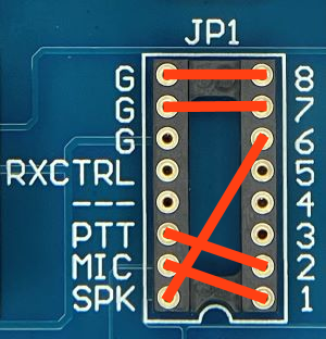
6-pin Mini DIN Data Port Connector - Use SignaLink USB p/n SLUSB6PM or radio cable p/n SLCAB6PM
| SignaLink USB Jumper Socket | Pin-out | Radio Models | Notes |
|---|---|---|---|
|
|
Pin 1 – Data In Pin 2 – Ground Pin 3 – PTT Pin 4 – 9600 Out Pin 5 – 1200 Out Pin 6 – Squelch |
TM-255 TM-271** TM-271A** TM-451 TM-455 TM-733A TM-D700 TM-D700A TM-D710 TM-D710A TM-D710E TM-G707 TM-V7 TM-V7A TM-V71A TM-V708 TS-480HX TS-480SAT |
For VHF/UHF modes that require 9600 baud audio
(VARA FM Wide), you will need to move the SPK jumper to pin #4 and configure
your radio for 9600 baud audio (see your radio manual for details). **Only European models of the TM-271 and TM-271A have a 6-pin mini-DIN Data Port. For non-European models, you'll need to attach the SignaLink to the radio's RJ-45 Mic jack. |
13-pin DIN Accessory Port Connector
- Use
SignaLink USB p/n
SLUSB13K
or radio cable p/n
SLCAB13K
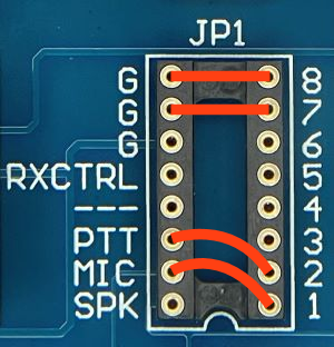
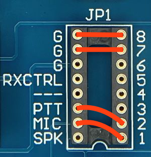
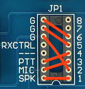
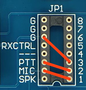
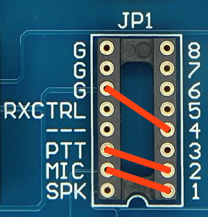
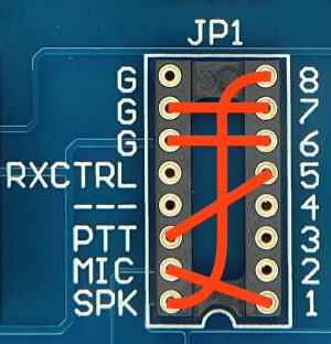
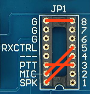
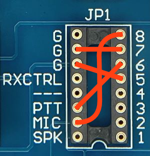
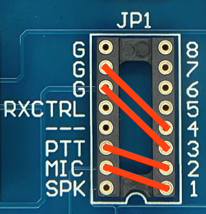
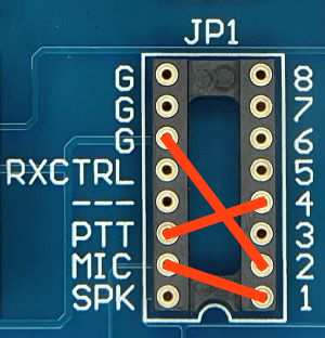
NOTE: Our SLCAB13K cable works with ALL Kenwood radio's that have a 13-pin Accessory Port. However there are three possible settings for the PTT jumper. If your radio is not listed below in Figure 1 or Figure 2, then you will need to try both jumper settings to determine which PTT configuration your radio requires. We suggest that you try the settings in Figure 1 first. Please note that your radio will NOT be damaged if you install the PTT jumper using the wrong configuration - you just won’t be able to transmit properly (no power output, hot mic, etc.). After you have installed the jumpers, be sure to set the sound card audio levels as outlined in the SignaLink manual. If you do not set the levels correctly, then the SignaLink may not transmit, and you might mistake the problem for incorrect jumper settings.
|
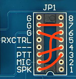
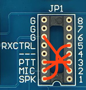
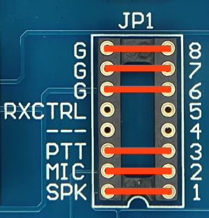
Figure 1 |
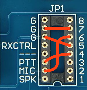
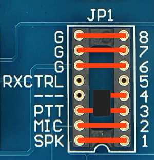
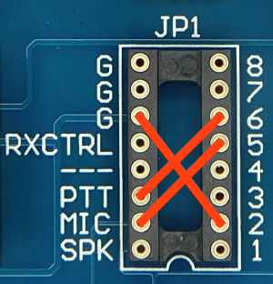
Figure 2 |
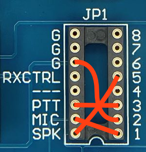
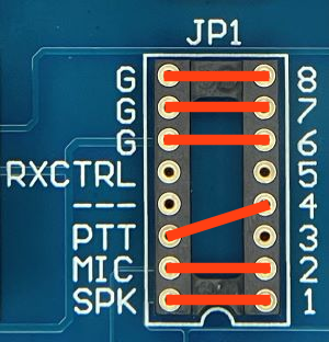
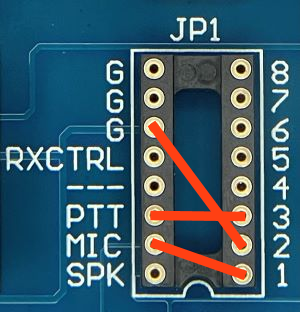
Figure 3 |
Notes |
|
This configuration is the most common. It works with most Kenwood radios including the TS-140, TS-450S, TS-570D, TS-590S, TS-680, TS-690, TS-850, TS-870, TS-890S, TS-950, TS-990, TS-2000 and the TS-2000X. |
This configuration is less common and is used by some older radios such as the TS-440, TS-711 and TS-811. Note that these settings are identical to those in Figure 1, except for the PTT jumper, which has been replaced by a dual diode module (supplied with cable p/n SLCAB13K). If you have lost your dual diode module and need to build a replacement, it is made using two 1n914 diodes (or similar). The striped (cathode) ends of each diode are connected together and plug into the JP1 PTT pin (solder one diode to the other and then plug in ONE diode lead only - do not try to plug in both leads or you'll damage the socket). The anode end of one diode goes to JP1 pin #3 and the anode end of the other diode goes to JP1 pin #4. Be sure the diodes you use are the same lead size as our jumper wires (24 awg) or slightly smaller. Larger diode leads may damage the JP1 socket. |
This configuration is used by the TS-940. |
TS-2000
users should set menu item 50E to Main and 50F
to 1200 Baud. Menu 50B can be used to increase the radio's power output
if it is too low. Menu 50C can be used to adjust the Receive Audio level.
To avoid a possible bug in the radio firmware, we suggest that you change these menu items even if they
already appear to be set correctly (set 50F to 9600,
and then back to 1200, etc.).
TS-570 users should set Menu #33 to 1 or 2 (a setting of zero will result in no transmit power). Menu #34 should be set at 4-5 and can be increased to provide more Receive Audio if needed. TS-440 users please note that your radio's Mic Gain control will affect your power output. We suggest setting this control to 75% and then adjusting it as needed so that the SignaLink's TX knob can be used to adjust the power output properly. Many users of this radio also report the need to enable SignaLink jumper JP3 for more Transmit Audio.
|
4-Pin Round Mic Connector - Use SignaLink USB p/n SLUSB4R or radio cable p/n SLCAB4R
| SignaLink USB Jumper Socket | Pin-out | Radio Models | Notes |
|---|---|---|---|
|
|
Pin 1 – Mic Input Pin 2 – GND Pin 3 – N/C Pin 4 – PTT |
13-510 | Speaker audio is not available on the mic jack, so you will need to connect the supplied audio cable as outlined in the SignaLink USB manual. |
RJ-45 Mic Connector - Use SignaLink USB p/n SLUSBRJ4 or radio cable p/n SLCABRJ4
| SignaLink USB Jumper Socket | Pin-out | Radio Models | Notes |
|---|---|---|---|
|
|
Pin 1 –
N/C Pin 2 – GND Pin 3 – N/C Pin 4 – N/C Pin 5 – Mic Input Pin 6 – PTT Pin 7 – N/C Pin 8 – N/C |
HTX-212 HTX-242 |
Speaker audio is not available on the mic jack of these radios, so you will need to connect the supplied audio cable as outlined in the SignaLink USB manual. |
8-Pin Round Mic Connector - Use SignaLink USB p/n SLUSB8R or radio cable p/n SLCAB8R
| SignaLink USB Jumper Socket | Pin-out | Radio Models | Notes |
|---|---|---|---|
|
|
Pin 1 –
Mic
Pin 2 – PTT Pin 3 – NC Pin 4 – NC Pin 5 – NC Pin 6 – RX Audio Pin 7 – Mic GND Pin 8 – GNC |
SGC-2020 |
|
4-Pin Round Mic Connector - Use SignaLink USB p/n SLUSB4R or radio cable p/n SLCAB4R
| SignaLink USB Jumper Socket | Pin-out | Radio Models | Notes |
|---|---|---|---|
|
|
Pin 1 – Mic Input Pin 2 – GND Pin 3 – PTT Pin 4 – N/C |
Corsair I 560 Corsair II 561 Omni VI Pegasus Scout |
Speaker audio is not available on the mic jack of these radios, so you will need to connect the supplied audio cable as outlined in the SignaLink USB manual. These jumper settings work with virtually all Ten-Tec 4-pin Mic jacks. However you should verify that your radio has the same pin-out before installing them. |
5-Pin DIN Accessory Connector - Use SignaLink USB p/n SLUSB5PD or radio cable p/n SLCAB5PD
| SignaLink USB Jumper Socket | Pin-out | Radio Models | Notes |
|---|---|---|---|
|
|
Pin 1 - Mic Input Pin 2 - GND Pin 3 - PTT Pin 4 - AF Output Pin 5 - NC |
Argonaut V Jupiter** Omni VII |
Jupiter - This radio must be in "Line" to use the ACCY jack
(see your radio manual for details).
|
8-Pin DIN Accessory Connector - Argonaut VI, Eagle, Orion & Orion II Only - Use SignaLink USB p/n SLUSB8PD or radio cable p/n SLCAB8PD
| SignaLink USB Jumper Socket | Pin-out | Radio Models | Notes |
|---|---|---|---|
|
|
Pin 1 - Aux In Pin 2 - GND Pin 3 - PTT Pin 4 - Line Out Pin 5 - NC Pin 6 - Line Out Pin 7 - FSK Pin 8 - NC |
Argonaut VI Eagle Orion** Orion II** TEN-TEC Delta II Users: Our 8-pin DIN cable is NOT compatible with the TEN-TEC Delta II. You must connect the SignaLink to this radio's 4-pin Mic jack.
|
Orion (original model) - The "Audio" menu determines what audio is available on pins 4 and 6, so the SPKR jumper will need to be set accordingly.
Orion II - Pin #4 is ALWAYS the audio output. |
RJ-45 Mic Connector - Use SignaLink USB p/n SLUSBRJ4 or radio cable p/n SLCABRJ4
| SignaLink USB Jumper Socket | Pin-out | Radio Models | Notes |
|---|---|---|---|
|
|
Pin 2 – Pin 3 – Pin 4 – Pin 5 – Mic Input Pin 6 – PTT Pin 7 – Pin 8 – |
|
Speaker audio is not available on the mic jack of these radios, so you will need to connect the supplied audio
cable as outlined in the SignaLink USB manual.
|

|
Pin 2 – Pin 3 – Pin 4 – Pin 5 – GND Pin 6 – MIC Pin 7 – PTT Pin 8 – |
TH-9000D |
Speaker audio is not available on the mic jack of these radios, so you will need to connect the supplied audio
cable as outlined in the SignaLink USB manual.
|
4-Pin Round Mic Connector - Use SignaLink USB p/n SLUSB4R or radio cable p/n SLCAB4R
| SignaLink USB Jumper Socket | Pin-out | Radio Models | Notes |
|---|---|---|---|
|
|
Pin 1 –
GND
Pin 2 – Mic Input Pin 3 – PTT Pin 4 – N/C |
FT-7B FT-101 FT-101ZD FT-221 FT-225 FT-227R FT-901DM |
Speaker audio is not available on the mic jack
of these radios, so you will need to connect the supplied audio
cable as outlined in the SignaLink USB manual. |
8-Pin Round Mic Connector - Use SignaLink USB p/n SLUSB8R or radio cable p/n SLCAB8R
| SignaLink USB Jumper Socket | Pin-out | Radio Models | Notes |
|---|---|---|---|
|
|
Pin
1 – N/C Pin 2 – N/C Pin 3 – N/C Pin 4 – N/C Pin 5 – N/C Pin 6 – PTT Pin 7 – GND Pin 8 – Mic Input |
FT-102 FT-107 FT-107M FT-290 FT-707 FT-726R FT-736 FT-736R FT-747 FT-757 FT-757GX FT-767GX FT-840 FT-847** FT-890** FT-920** FT-950** FT-980** FT-990** FT-1000 FT-1000D** FT-1000MP** FT-2000 FT-5100 FT-DX1200 FT-DX3000** FT-DX5000** |
Speaker audio is available on
some radio models. Check
your radio manual and install the SPK jumper only if this signal is
provided. If it is not, then you will need to connect the supplied audio
cable as outlined in the SignaLink USB manual.
**On the FT-890, FT-980, FT-990, FT-1000 and the FT-1000D, you should also jumper Pin #2 and Pin #5 to Ground. **On the FT-847, FT-920, FT-950, |
RJ-11 Mic Connector - Use SignaLink USB p/n SLUSBRJ1 or radio cable p/n SLCABRJ1
| SignaLink USB Jumper Socket | Pin-out | Radio Models | Notes |
|---|---|---|---|
|
|
Pin 2 – N/C Pin 3 – +9V Pin 4 – GND Pin 5 – Mic Input Pin 6 – SW1/PTT |
FT-90R FT-100** FT-1500M FT-1802 FT-1900R FT-2600 FT-2800M FT-2900R FT-2980R FT-3185 FT-7800R FT-7900R FT-8900R FTM-300 FTM-350 FTM-350R FTM-350AR FTM-400DE FTM-400DR FTM-400XDE FTM-400XDR FTM-3100R FTM-3200DR FTM-7250DR |
Speaker audio is not
available on the mic jack of these radios, so you will need to connect the supplied audio
cable as outlined in the SignaLink USB manual. FT-100 - The PTT jumper MUST be replaced with a standard 1/4 watt 27k resistor. Some other Yaesu models with an RJ-11 Mic jack might also use these same settings (check your radio manual). |
RJ-45 Mic Connector - Use SignaLink USB p/n SLUSBRJ4 or radio cable p/n SLCABRJ4
| SignaLink USB Jumper Socket | Pin-out | Radio Models | Notes |
|---|---|---|---|
|
|
Pin 2 – N/C Pin 3 – N/C Pin 4 – Pin 5 – Mic Input Pin 6 – PTT Pin 7 – Pin 8 – N/C |
FT-2400 FT-2500 VX-2000U** VX-2100** VX-2200** VX-3000U** |
Speaker audio is available on
some radio models. Check
your radio manual and install the SPK jumper only if this signal is
provided. If it is not, then you will need to connect the supplied audio
cable as outlined in the SignaLink USB manual.
**These radios provide differential audio
output on the radio's External Speaker jack. You MUST use a cable with
a built-in audio isolation transformer to attach this output to the
SignaLink or you may damage the radio. |
|
Pin 2 – N/C Pin 3 – N/C Pin 4 – Mic GND Pin 5 – Mic Pin 6 – PTT Pin 7 – GND Pin 8 – N/C |
FT-450 FT-600 FT-817 FT-857 FT-897 FT-991 FT-991A VX-2100 VX-2200 |
Speaker audio is available on
some radio models. Check
your radio manual and install the SPK jumper only if this signal is
provided. If it is not, then you will need to connect the supplied audio
cable as outlined in the SignaLink USB manual.
|
5-Pin Din Packet Connector - Use SignaLink USB p/n SLUSB5PD or radio cable p/n SLCAB5PD
| SignaLink USB Jumper Socket | Pin-out | Radio Models | Notes |
|---|---|---|---|
|
|
Pin 1 – Data In Pin 2 – GND Pin 3 – PTT Pin 4 – Data Out Pin 5 – NC |
FT-920** FT-1000** FT-1000D** FT-1000MP** FT-1000MPMKV-Field** FT-2000 FTDX-5000/D/MP FTDX-9000/D/MP |
FT-920
- The AFSK/FSK switch MUST be set
to AFSK, and the radio must be in the "Data" mode (push the
radio's front panel
"Data" button). The Mic Gain control appears to affect the
operation of the Packet jack, so we suggest setting this to 50% and then
adjusting as needed. FT-1000 / FT-1000D - The 5-pin DIN jack on this radio supports only FM and LSB, which are not compatible with the majority of digital modes. We recommend connecting the SignaLink to the Mic jack instead. FT-1000MP - Detailed setup information for this radio is available thanks to Wade Bolling, W5ERX. Please click here for details. FT-1000MPMKV / FT-1000MPMKV Field - These radios MUST be in the Packet mode for digital operation (NOT USB/LSB). For FT8, PSK and other digital modes that use USB, you'll need to set your radio's "User Mode" (selection 8-6) to "PS31U". This will configure the radio to look at the Packet jack and use the correct side band. For more detailed information on this (including settings for other modes), see "Digital Modem Operation" in your radio manual. |
6-pin Mini DIN Data Port Connector - Use SignaLink USB p/n SLUSB6PM or radio cable p/n SLCAB6PM
| SignaLink USB Jumper Socket | Pin-out | Radio Models | Notes |
|---|---|---|---|
|
|
Pin 1 – Data In Pin 2 – Ground Pin 3 – PTT Pin 4 – 9600 Out Pin 5 – 1200 Out Pin 6 – Squelch |
FT-100D FT-450** FT-817 FT-817ND FT-818 FT-840** FT-847** FT-857 FT-891 FT-897 FT-950** FT-991 FT-991A FT-1500M FT-7100 FT-7800R FT-7900R FT-8000 FT-8100 FT-8500 FT-8800R FT-8900R FTDX-101D FTDX-1200 FTDX-3000 FTM-100DR** FTM-200DR** FTM-300** FTM-350** FTM-350R** FTM-350AR** FTM-400DE** FTM-400DR** FTM-400XDE** FTM-400XDR** FTM-500DE** FTM-500DR** FTM-6000R** VX-1700
|
For VHF/UHF modes that require 9600 baud audio
(VARA FM Wide), you will need to move the SPK jumper to pin #4 and configure
your radio for 9600 baud audio (see radio manual for details).
FT-450 - Some users have reported that this radio has a very sensitive Data Port, making power adjustments with the SignaLink USB's TX knob somewhat touchy. If this is the case with your radio, then please click here for a simple solution to this problem. FT-840 / FT-847 - The 6-pin mini-DIN Data Port on these radios supports FM and LSB only making it incompatible with most digital modes. On the FT-847, this jack also appears to function only on the VHF/UHF bands. Unless you are running digital modes that use LSB or FM you will need to connect the SignaLink to the Mic jack, or in the case of the FT-847, the Data I/O jack. FT-950 - Some users of this radio have reported that the Notch Filter is turned on after a hard reset. If you see a "hole" in your waterfall display, then please make sure that your Notch Filter is turned OFF. FTM-100DR, FTM-200DR, FTM-350 Series - This radio requires Yaesu's CT-141 adapter to convert from a 8-pin mini-DIN connector to a standard 6-pin mini-DIN. This adapter is available from a Yaesu dealer. |
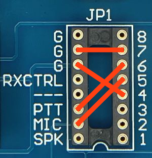
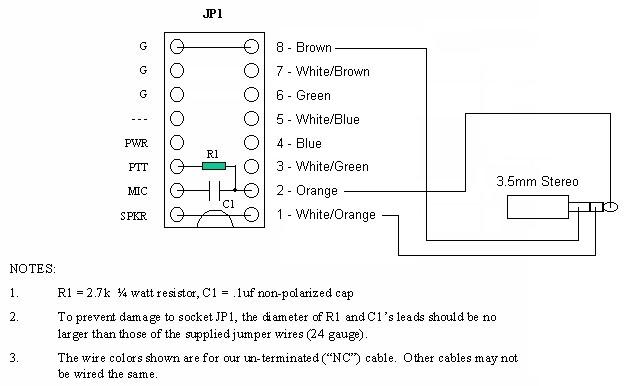
FT-847 ONLY - 3.5mm Stereo "Data I/O" jack for HF ONLY - Use SignaLink USB p/n SLUSB847 or radio cable p/n SLCAB847
NOTE: A fully assembled radio cable and jumper module (with built-in cap/resistor) is available for this connection. Order radio cable p/n SLCAB847 and jumper module p/n SLMODHT.
If you would like to operate the FT-847 on other bands, then you'll need to connect the SignaLink to either the Mic jack (this works on all bands for virtually all modes), or the 6-pin mini-DIN Data Port (this is for VHF/UHF FM or LSB modes only, not HF).
The values shown below for R1 and C1
have been used for decades in a number of our products.
You can use these values, or those shown in the FT-847 manual. Both will
work just fine.
|